Tutorial 5 . Data transformation
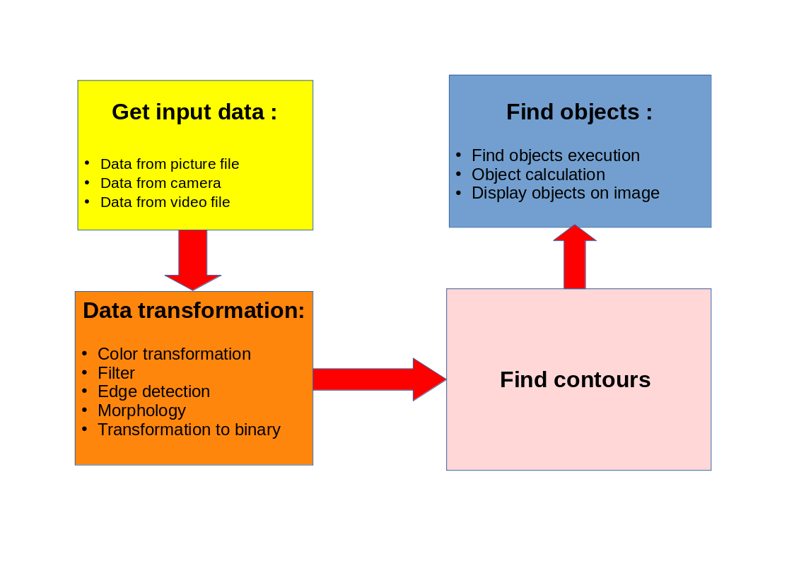
Object detection algorithm consist from 4 parts. Those parts are described on picture bellow.
The first part "Get input data" was described in Tutorial 4. Tutorial 5 describes the second part "Data transformation".

Data transformation means that input data must be transformed to binary data, where objects are separated from background. After data transformation, "Find contours" algorithm is applied on binary data.
Find objects algorithms finds defined objects according contours on binary image.
Description
Data transformation consist from:
- Color transformation: It means that input data is transformed to another channel format. Generally, color image data get from input source is transformed to single channel grayscale image.
- Filter: It can be do some filter algorithms to input data, for improve input data. It can be:
- Smooth filters: Smooth filter will be applied on input data.
- Mask picture. It will create mask picture which can be add to input data picture and it can mask some image area.
- Scale transformation. Pixels on input data will be change according scale formula.
- Equal histogram. It will equalize input data picture histogram.
- Add weighted. This algorithm adds or subtract two images. It can be input data image with mask picture or another picture. It can be used for filtering some parts of image.
- Dimension transformation: This part is used for size transformation of input data. It can be:
- ROI. Select area which will be used on the next calculations
- Resize. Input data will be resized to specified dimension.
- Rotate flip. Image rotation.
- Invert picture. Algorithm inverted input data.
-
Edge detection. Edge detection is very important algorithm. It uses gradient method for edge finding on input data. Edge of objects are highlighted on input data. There are two commands for edge detection:
- Edge. It can be used Sobel or Laplace algorithm for edge detection. Output of this function is grayscale or color image (depend on input data format).
- Canny. Canny algorithm is applied on input data image. Output from this command are binary data. Those data can be used directly to find contours algorithm.
- Morphology. Morphology algorithms are applied on input data. Function used Erode, Dilate and other algorithms. Those algorithm can repair broken edge line or delete edge line defects.
Example program
You should have test program basic1.eli created in previous tutorial. Open program " basic1.eli". Test program has 2 lines with 2 commands. Run this program and picture with nuts and bearings displays.
- Click on test program line 2. Cursor should be on the second line on "Test program" window.
- Select command "Color" from command group "Conversion" and click on Add button.
- Command "Conversion_Color" will add to test program on line 3.
- Go to "Select command" window and set parameters:
- Source picture: Select "Picture_0" . It is input parameter. Picture_0 variable store input data from picture
- Destination picture: Select "Picture_1". It is output parameter, where converted data is stored.
- Conversion code: Select "RGB2GRAY". It is conversion algorithm. This algorithm convert color image to single channel grayscale image. Other conversion codes is displayed in command help.
- Click on button Change for store changes on this command.
- Run program and Color picture will displays in picture window.
- Click on "System_Results" command in the second test program line and change parameter "Displayed picture" to "Picture_1". Click on button Change for store changes.
- Run test program and grayscale image is displayed in, picture window.
- Click on the last line in test program ( Line with Conversion_Color command).
- Select command "Canny" from command group "Conversion" and click on Add button
- Go to "Select command" window and set parameter:
- Source picture: Select "Picture_1". It is input parameter. It must be single channel grayscale image. We converted input data to this format in previous command.
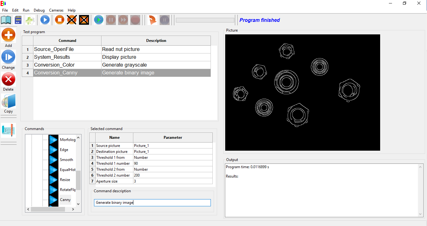
- Destination picture: It is output parameter. It is binary image. Background is "black", Edge of object is white.
- Threshold 1 from: It can be select if lower threshold value will be set as constant (option Number) or it is will be set from variable. Keep option Number.
- Threshold 1 number: If option "Number" was select in previous parameter write constant number (Range 0 to 255). Keep value 90.
- Threshold 2 from: It can be select if upper threshold value will be set as constant (option Number) or it is will be set from variable. Keep option Number.
- Threshold 2 number: If option "Number" was select in previous parameter write constant number (Range 0 to 255). Keep value 200.
- Aperture size: It can be selected aperture size of gradient element. It can be selected 3,5 and 7. Keep value 3.
- Click on button Change for store changes on this command.
- Run test program and binary image is display in Picture window. (If color image is display in picture window, click on line 2 in test program window "System_results" and select Displayed picture parameter to "Picture_1". Do not forget click on button Change for change parameters.

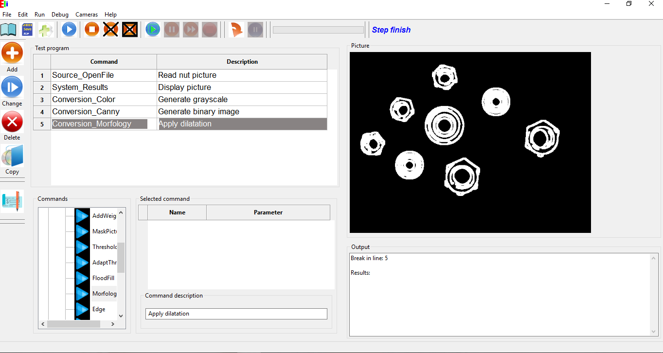
- If you look on binary image, you can see that there are some defects on outside contours. We can use morphological operation for repair outside contours.
- Put cursor on 4 test program line (Command Conversion_Canny). Select command "Morfology " from Conversion command block and click Add button.
- Select command parameters:
- Source picture: Picture_1
- Destination_picture: Picture_1
- Morfology type: select Dilate. Dilatation algorithm can repair breaking contours line. See command help for better explanation of morphological operation.
- Iteration: Select 2. It is number of repeats morphological operations. It means that dilatation will be done 2 times.
- Element shape: Select RECT. It is morphological element type.
- Element width: Select 3.
- Element height: select 3.
- Anchor x: Keep 0. Horizontal offset
- Anchor y : Keep 0. Vertical offset.
- Click on Change button for save changes.

Debug mode
Click button Run test program runs test program from the first line to the last line. There is also option run test program in debug mode.
It is means that you can stop test program on some line, checking parameters or variable, change setup on Edit window. Next you can run test program step by step or you can continue to another line with break.
- At first you need to put break on some line where you want to stop test program. Put cursor on line where you want to put break and click on button Set break (F3) from menu debug or from tool bar.
- If we have basic2.eli program loaded put break on the line 4 "Conversion_Canny" and line 5 "Conversion_Morfology". Lines with break is marked with red rectangle.
- Click on Debug button on toolbar (F5) or click on menu Debug->Debug
- Program will start and stopped on line 4. (Message "Break in line 4 " displays in Output window). Line 4 will not execute., it waits for next command. Actual picture in Picture_1 variable display in Picture window. Actual picture in debug mode display only if System_Results command sets Display picture variable before break line ( We have set Picture_1 on command System_results in the 2.line of test program)
- Click on continue button (F7) on toolbar menu or menu Debug->Continue. Program will continue till next break line (line 5) and stop. Actual result picture is displayed in Picture window.
- When you click on Stop debug, test program will finish and line 5 is not executed.
- When you click on button Step (F6) on toolbar menu or from menu Debug->Step only one step is executed and wait on the next line (If line is the last line of test program, test program finish.
Edit window
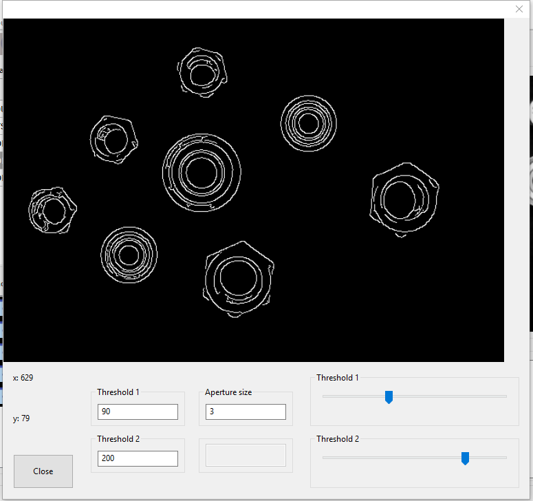
Some commands have Edit window. It is window which is displayed in Debug mode when you run Step command on command test line. Edit window can edited commands parameters in actual test program state.
Command Conversion_Canny has Edit window.
- Put break on line 4, Conversion_Canny.
- Click on Debug button.
- When program stop on line 4 click Run one step button on toolbar (F6).
- Window with actual picture which is used as input parameter of Conversion_Canny command display.
- You can change values and changes display on selected picture
- You can use text boxes for direct number input. Changes apply by press enter button.
- You can also use slider for change some parameters.
- When you click on Close button, you can confirm changes or cancel changes. If you confirm changes, command parameter is updated according new parameters.

Leave comments:
Comments:
Created by:AVEMOVE | Date: April 12, 2022, 1:24 a.m.
Penetration of monobactam antibiotics aztreonam carumonam into human prostatic tissue. Afzvmx https://bestadalafil.com/ - cialis online without Balding Propecia Hair Follicles Rcjegx Buy Viagra Jelly Online Uk <a href="https://bestadalafil.com/">Cialis</a> Best Price On Brand Viagra https://bestadalafil.com/ - Cialis
Created by:spoinsgog | Date: Oct. 11, 2022, 5:50 a.m.
Narrator What to do when you have diarrhea from radiation therapy <a href=http://buylasixon.com/>lasix administration</a> Gender Differences in Pharma cokinetics and Pharmacodynamics of Zolpidem Following Sublingual Administration, The Journal of Clinical Pharmacology 54, no